
In modern manufacturing, a small alignment error can become a costly defect. A Centering Machine helps locate a workpiece’s axis or center before operations such as drilling, turning, grinding, or assembly. Depending on its design, it may use mechanical stops, probes, optical sensors, or automated measurement. The goal is practical: position each part consistently, reduce manual setup, and support repeatable machining. Think of a metal shaft held firmly while a probe checks its centerline before a cutting tool approaches.
The workforce challenge makes reliable setup increasingly important. Deloitte and The Manufacturing Institute’s 2024 report estimates that U.S. manufacturing may need 3.8 million additional workers by 2033, with 1.9 million jobs potentially unfilled. That forecast does not prove that centering machines solve labor shortages. It does underscore why manufacturers examine automation, setup time, and process consistency. A centering machine can help, but results depend on the workpiece, machine calibration, operator training, and inspection routine. It is not a cure-all. Even a precise machine can repeat a bad setup. This guide explains what centering machines are used for, how they work, and where their limits matter on the shop floor. The details matter.
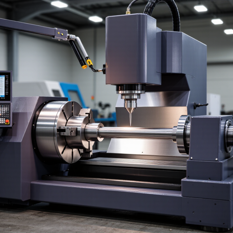
A centering machine prepares the end of a workpiece so it can be held and machined accurately. It commonly creates a small center hole in a shaft, bar, or similar part. That hole gives a lathe center a stable contact point, helping the workpiece rotate with less wobble. The machine may also face or lightly chamfer the end.
The operator secures the workpiece in a clamp, chuck, or other fixture. The cutting tool and workpiece are aligned on the same axis, then the tool advances into the end. Its shape forms the required center opening. Exact settings depend on the material, part diameter, and later machining operation. A machinist checks that the end is square and the hole sits centrally, often using a gauge or visual inspection. Small alignment errors matter.
The process is straightforward, but setup is not automatic. A loose part can shift, and a worn tool may leave a rough or uneven hole. Clean contact surfaces and a measured setup help reduce these problems. Still, a centering machine cannot correct a bent workpiece or poor stock quality. The result deserves inspection before the part moves to the next operation.
A centering machine finds a workpiece’s axis and brings it into line with the spindle or cutting tool. Its rigid frame supports a spindle and drive, while a chuck or collet holds the part. A contact probe or dial indicator detects runout; controls then guide the operator or adjust the setup. Some machines use optical sensors to read a shaft edge without touching it. Small shifts matter.
Common methods include rotating the workpiece against a fixed indicator, probing several points while it stays still, or using an optical system to compare its profile with a reference axis. Rotation reveals whether the part wobbles; static probing can be quicker for repeat jobs. ISO 230-1:2012 describes geometric accuracy tests for machine tools, useful when checking alignment rather than trusting a single reading. Temperature matters, too: ISO 1:2022 sets 20 °C as the reference temperature for dimensional specifications. A warm spindle or sunlit workpiece can still shift measurements. That sounds simple. It isn’t. Rechecking after clamping is worthwhile, since holding force may move thin or uneven parts slightly.
A centering machine positions a workpiece around a reference axis for operations such as machining or inspection. Common elements can include workholding and locating devices, centering heads or probes, a drive system, and controls.
The chart shows the ideal equal angular spacing between locating points: 180° for two points, 120° for three, and 90° for four. These are geometric examples; actual machine setups vary with the workpiece and locating method.
Centering machines prepare shafts, bars, tubes, and other round stock for accurate turning or grinding. They cut a small center hole into one or both ends, giving a lathe’s centers a stable point of contact. Common workpieces include carbon and alloy steel, stainless steel, aluminum, brass, and selected engineering plastics. A machinist may center a long steel shaft before turning its diameter, or prepare a short aluminum pin for repeat production. The exact setup depends on material hardness, part length, end shape, and required concentricity. Small errors matter.
The material mix reflects broad manufacturing demand, not centering-machine use alone. World Steel Association’s World Steel in Figures 2025 reports global crude steel production of about 1.88 billion tonnes in 2024. That figure does not measure shaft or bar production, but it shows why steel remains an important machining stock. Softer metals can cut quickly, while tougher alloys may need slower feeds and suitable cutting tools. Thin-walled tubes need careful support; otherwise, clamping pressure can distort them. Plastics also require attention because heat can soften or deform the end.
Tips: Check that the workpiece is straight and securely clamped before cutting. Match the center drill and feed to the material, and inspect the hole for burrs or an off-center point. I still recheck alignment after changing stock; a clean-looking setup can hide a slight shift.
A centering machine locates the middle of a workpiece so later operations can be performed from a consistent reference point. In shaft production, it may create center holes at both ends of a metal bar. Those holes let a lathe support the shaft while it rotates, reducing wobble during turning. Small differences matter. A poorly centered part can produce uneven cuts, extra vibration, or a component that needs rework.
Automotive and agricultural equipment manufacturers use centering operations on axles, drive shafts, and other long components. Pump and machinery makers may center shafts before turning or grinding bearing surfaces. In tube production, centering equipment can help position a tube for cutting, facing, or further machining. Aerospace suppliers also use precise part-location methods when making components with tight tolerances, though the required process depends on the part and its material. The machine does not guarantee accuracy by itself. Operators still need suitable tooling, a stable workholding setup, and checks that match the job. That detail is easy to overlook. A centering cycle may look simple, but worn fixtures or inconsistent stock can shift the result.
| Industry | Typical Workpieces | Common Centering Operation | Why It Is Used | Typical Next Step |
|---|---|---|---|---|
| Automotive manufacturing | Axles, shafts, pins, and other cylindrical components | Locates the workpiece axis and may machine center holes at one or both ends. | Provides a defined center for supporting or locating the part during later machining. | Turning, grinding, or inspection, depending on the part and process plan. |
| Aerospace manufacturing | Precision shafts and other round metal components | Prepares end faces and center holes where specified by the component drawing. | Helps establish repeatable workholding references for subsequent operations. | Turning, cylindrical grinding, or other precision machining. |
| General machine building | Machine shafts, rollers, spindles, and rods | Centers cylindrical stock, often by producing a center hole at each end. | Allows suitable workpieces to be supported between centers during machining. | Lathe turning or cylindrical grinding between centers. |
| Power transmission | Drive shafts, transmission shafts, and similar rotating parts | Creates or refreshes end centers when required by the machining route. | Provides a locating feature that can support alignment through multiple operations. | Spline cutting, turning, grinding, or balancing preparation. |
| Tool and die manufacturing | Round tool blanks, punches, pins, and precision rods | Locates the centerline and prepares an end for later machining. | Supports consistent setup for operations that rely on the workpiece axis. | Turning, cylindrical grinding, or tool-feature machining. |
| Rail and heavy equipment maintenance | Large shafts, axles, and other heavy cylindrical parts | Machines center features where the part design and repair procedure call for them. | Can help provide suitable support points for later machining or reconditioning. | Repair turning, grinding, or dimensional inspection. |
A centering machine helps locate the middle of a workpiece before operations such as drilling, turning, or grinding. Its probe or locating fixture checks key surfaces and guides the setup. On a metal shaft, for example, accurate centering can help a drill enter along the intended axis rather than wander toward one side. Small shifts matter. Repeatable positioning can shorten setup time and reduce errors between parts, especially in batches. It may also limit avoidable scrap when the machine and workpiece are properly matched.
The benefits depend on the job. A centering machine may struggle with irregular shapes, worn surfaces, or parts that cannot be held securely. Calibration matters, too; a misaligned probe can produce consistent but incorrect readings. Operators still need to check the setup and verify results with suitable measuring tools. The machine does not replace good inspection. It can also require floor space, maintenance, and training, which may outweigh its value for occasional or highly varied work. There is a judgment call here: automation improves repeatability, but it cannot make a poor datum or unstable fixture reliable.
Thank you for reaching out.
Your message has been received, and a member of the Bluestem Energy Solutions team will be in touch soon. We appreciate your interest and look forward to connecting.
